
THE “BEGINNING”
Having access to a cutting plotter by Elitron ( https://elitron.com/en/cam/kombo-sd-plus/) and an Agfa Jeti plotter (https://www.agfagraphics.com/global/en/product-finder/jeti-titan-s-hs.html) is a maker’s dream.
I decided to put my practical skills and my Lightwave experience to work and build the ultimate Mini Arcade Cabinet to house my recently restored Sega Megadrive.
I wanted to build a cabinet that would satisfy the following:
- Use a CRT screen for the ultimate Retro experience. I hooked up the MD on the 50 inch LCD and was appalled by the terrible square pixels. I decided to skip all the filtering and upscaling nonsense and go ahead with the true look.
- Use my Megadrive as it is with minimal destruction to its original form and function. It is, of course, moded with a 50/60 switch and a JAP/ENG switch.

- My Megadrive is a “high definition” model (one of the ones with the proper sound chip) (http://segaretro.org/File:IC_BD_M5_JPN_VA6.jpg) and I wanted to use the front stereo headphone jack as the audio output.
- I wanted my Multitap adapter to be as user accessible as possible.
- I wanted to use original industry standard Arcade Stick and buttons.
- I wanted a single ON switch or just a single power plug to turn the thing on.
- I wanted everything to be included in the cabinet which should be as small as possible because I wanted my wife to accept its existence in our living room 🙂
I started out by finding a CRT screen. I already owned a Philips VS0080 monitor ( https://www.youtube.com/watch?v=LLtDBsQ2c-c ) but it has seen better days. I sourced a couple of 15 inch TVs which were in much better condition but their PIN8 implementation in their SCART connector left a lot to be desired.
THE “PIN 8” INCIDENT
The Pin #8 in a SCART connector forces the TV to turn on and switch to AV (the external input) once it receives 5 or 12 volts (for 16/9 and 4/3 aspects respectively). This was essential to satisfy my #6 goal: You can’t have a true arcade cabinet if you need to press a couple of buttons on the front of the TV.
Now, my MD is fitted with a SCART cable (or retrofitted, damn if I can remember) but it simply does not send current to pin 8. There would have to be another source for the 12 volts. But I never got there because…
12 volts to PIN 8 would be my only option with TV #1 since it needed a button press to turn on and a second one to switch to AV. This TV always turns on to standby mode and the PIN8 signal does not force it to wake up. (It does switch it to AV but to 50Hz even when the signal is in 60Hz. Pressing the AV button fixes this but it still is two button presses). FAIL.
TV #2 completely FAILS to respond to any PIN8 voltage. To make matters worse, it doesn’t have an AV button on the box and you need the remote control. Nope.
So back to the Philips Monitor.
MEASURING
Taking the measurements of physical objects is not the easiest thing in the world especially when they are consumer products. The Philips monitor was reasonably square but the angles were still a problem. I started by drawing the perimeter of the monitor on a large foam board. It sort of worked but I wanted more precision. I gave up trying to put everything together in my mind and decided to make simplified models in Lightwave. 
Once I was satisfied with the form of the cabinet I translated all the sides into 2D drawings taking into account how each of the sides connects. I also created the artwork for the sides and the marquee taking into account the colors of our living room. This was critical. Seriously. I opted to create an Atari style retro stripe pattern.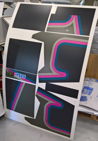
For the joystick panel I took into account the industry standard hole sizes for the buttons. Search for “HAPP joystick hole dimension diagram” and you shall find.
PRINTING AND CUTTING
I then combined all the printed sides into a single drawing and added the cutting lines.
I had access to a spare piece of 5mm FOREX (foam sheet of PVC) which has excellent properties regarding printing, very lightweight and easy to post process with tools like a box-cutter etc. I originally planned to use 10mm but opted to glue together 3 sheets for the sides resulting in 15mm thickness. The bottom is 10mm and the top and back covers are a single 5mm thickness. (check a video of the cutting here: https://youtu.be/yZ_aYEjvBVQ)
PUTTING IT TOGETHER
FOREX is amazing to work with as you can get away with only using Hot Glue to put together the whole thing. I had several small scraps of 10mm FOREX that I could use as spacers and support fixtures. I just put a little hot glue and snapped the small piece into place. Some screws were also used for removable panels and support bars. Fitting the monitor inside the cabinet was a matter of trial and error, adding and removing spacers to achieve the angle that I used in my Lightwave mockup.
 The speakers were hot glued into place
 Removable panels were added in the back. The top one is carrying the Multi adapter for the gamepads. The yellow button in the photo is a 3 contact button that is wired so that when pressed it opens the circuit. It is wired to the Megadrive’s power supply cable so that when pressed it emulates the reset button on the console. This way you don’t have to open the top cover to press it.
  The buttons were next. I originally planned to buy an industry standard HAPP stick and buttons from ebay but opted to check out a local supplier so that I could try their feel before buying.
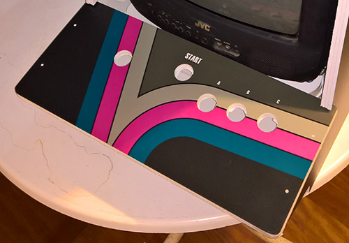 It turns out that the supplier is an actual manufacturer that has been providing the local cabinet makers with sticks and buttons since the good old days. Excellent! ( http://www.stamos-electronics.gr/stamos.asp?m=1&m1=Joystick ).
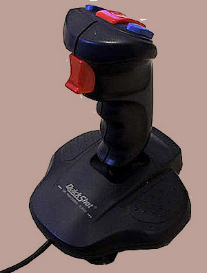
Since there is some multiplexing in the Megadrive controller I had to gut an existing controller to hook up the buttons. The joystick selected to be sacrificed was an “aviator” style Quickshot joystick. It was never any good at anything, especially all the arcade style games of the platform so, no harm done. Sourcing the chips necessary would be too much trouble, if at all possible, so I wouldn’t bother with that
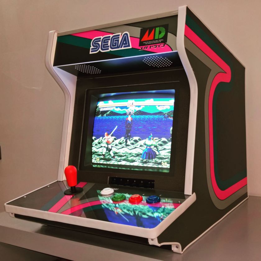
Here is the finished product with the last finishing touches on the controller bar trim. And here is the cabinet with the sliding top cover opened
Finally I went to rip an amplifier from a broken 5.1 PC speaker system: 5 months in the basement had a weird effect to the system. It appear to work ok. I hooked up the 2 speakers of the cabinet and left the Woofer/Amp unit outside. I would rather have everything included in the box as planned but the sound with the woofer is so awesome that I am willing to look the other way 🙂
Last Touches
I added a plexiglass cover on the joystick board to protect the artwork. Maybe I will add another one to cover the CRT screen. It’s now rigid and the artwork is completely protected.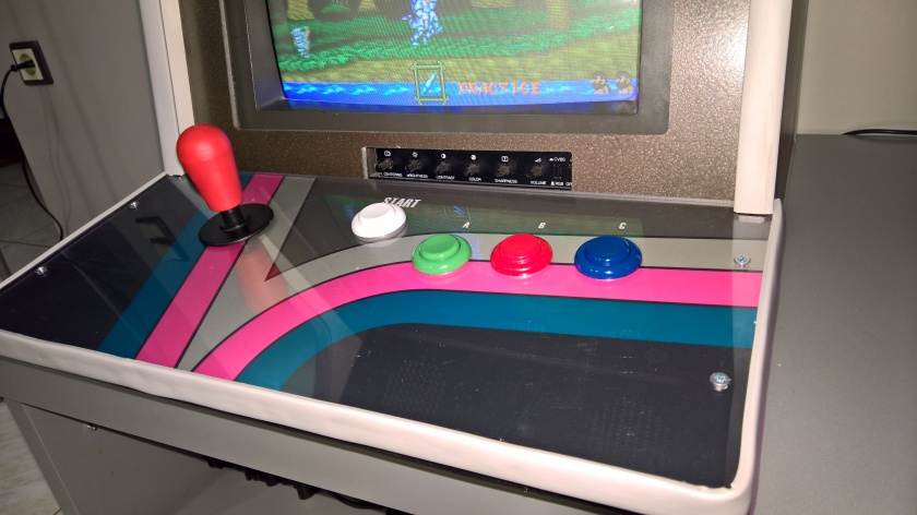
I also made some air vents as the CRT plus the MD make too much heat for a sealed box. Better have some air flow.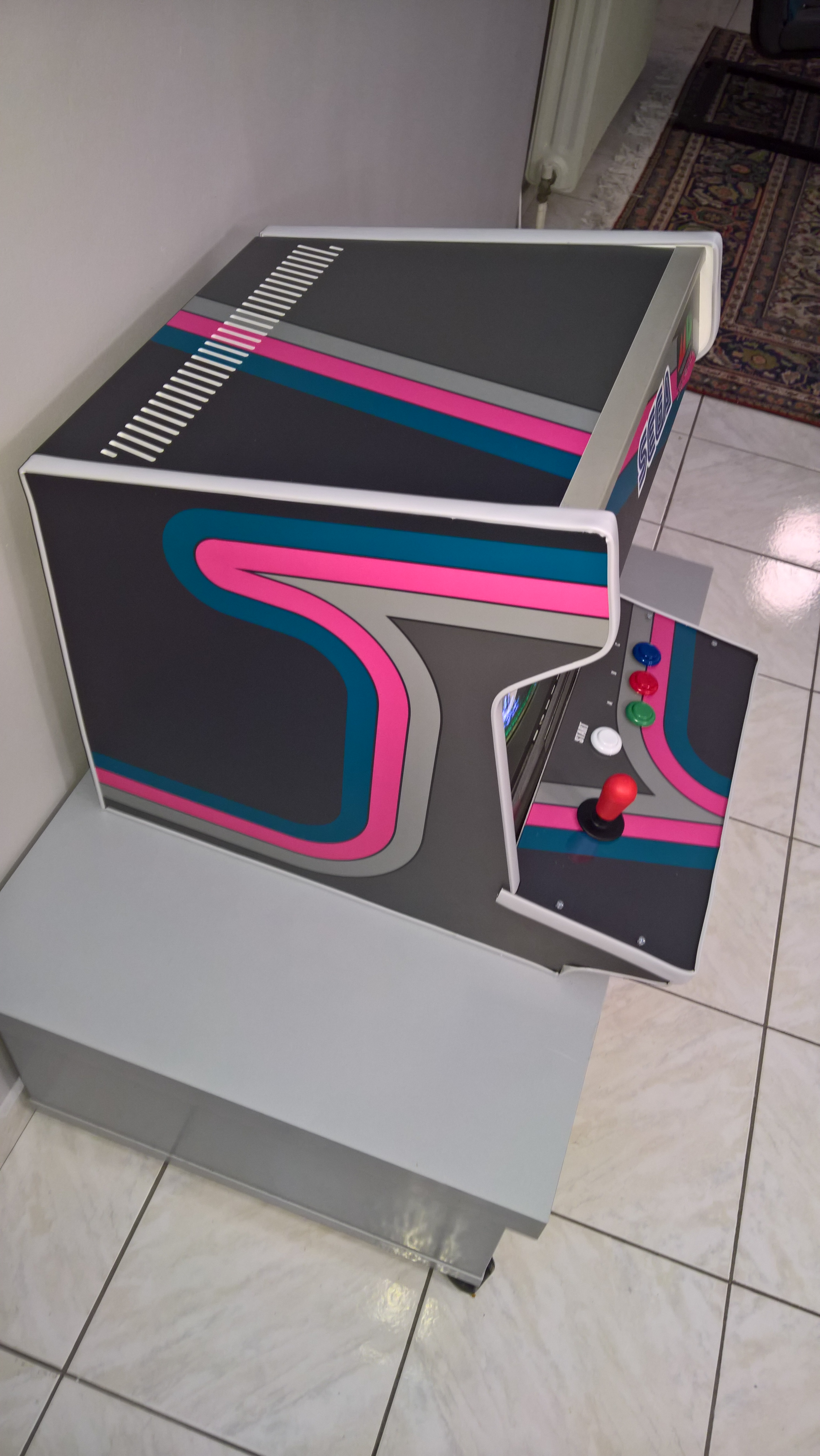
The Mega Everdrive SD X3 adapter is here. So far so good! More on that soon.
